
Data Sheet
In today's commercial environment, uninterrupted power is not a luxury; it's a necessity. From data centers to manufacturing facilities, a power outage can result in significant financial loss and operational chaos. This guide provides a comprehensive breakdown of the control systems that form the brain of a modern commercial backup power system, including how they function, how they integrate with battery storage, and what you need to know to ensure ultimate reliability.
At its heart, a generator (or "genset") is a machine that converts mechanical energy into electrical energy. In a commercial backup generator, this process starts with an internal combustion engine, similar to one in a large truck, which runs on diesel, natural gas, or propane. This engine turns a component called an alternator. The alternator uses the principle of electromagnetic induction—spinning magnets around coils of wire—to generate electricity. This entire system is supported by a fuel system to power the engine, a cooling system to prevent overheating, and an exhaust system to safely vent fumes.
The control panel is the human-machine interface (HMI) for the generator. It's the central hub for monitoring, controlling, and protecting the entire system. Early controllers were simple analog gauges and switches, but modern controllers are sophisticated computers/microprocessors. They provide real-time data on everything from voltage and current to oil pressure and coolant temperature. The controller is responsible for automatically starting and stopping the generator, sensing problems, and communicating with other building systems.
Here are the most common features you'll find on a controller:
Main Display Screen: This is usually a small LCD screen that shows the real-time status of the generator. You can typically scroll through different screens to see electrical data (voltage, frequency, amperage), engine data (oil pressure, coolant temperature, engine speed), and run-time hours.
Mode Selector: This is the most important switch. It usually has three positions:
OFF: This completely disables the generator. It will not start, even if the power goes out. This is used for maintenance and long-term shutdown.
MANUAL (or RUN): This allows an operator to start and stop the generator by pressing buttons on the panel. This is used for testing the generator itself without actually transferring the building's load to it.
AUTO: This is the normal operating mode. In "AUTO," the controller constantly listens for a signal from the Automatic Transfer Switch (ATS). If the utility power fails, the ATS signals the controller, which then automatically starts the generator.
Emergency Stop (E-Stop): This is a large, red, mushroom-shaped button. Pushing it will immediately and forcefully shut down the generator, bypassing all other controls. It's used for true emergencies, like a fire or catastrophic mechanical failure.
Alarm/Fault Lights: These are typically red or amber indicator lights. They illuminate when the controller detects a problem, such as low oil pressure, high engine temperature, or a failure to start. The display screen will usually give more detail about the specific fault.
When the power goes out, something needs to act as a "traffic cop" to disconnect the building from the dead utility grid and connect it to the live generator. This is the job of the Automatic Transfer Switch (ATS). How it performs this switch defines the experience for the building's occupants and equipment.
Standard Transfer (Open-Transition): The most common method uses an Automatic Transfer Switch. The ATS is connected to both the utility grid and the generator. When it senses a loss of utility power, it waits a moment, breaks its connection to the grid (open), and then connects to the generator (transition). This "break-before-make" process ensures the generator and grid are never connected at the same time (potentially hazardous during an outage) but causes a brief power interruption to the building for a few seconds.
Seamless Transfer (UPS Integration): For facilities that cannot tolerate any power loss (like hospitals or data centers), an Uninterruptible Power Supply (UPS) is used. A UPS is essentially a large battery system that sits between the utility power and the critical equipment. When the grid fails, the UPS provides power instantly with zero interruption. The generator controller then senses the outage and starts the generator. Once the generator is stable, the ATS switches the building load from the now-draining UPS to the generator for the long-term outage.
A power failure event is a highly choreographed sequence. Every step is timed and checked to ensure a smooth and safe transition. Here is the step-by-step sequence for a standard outage event:
Power Loss: The Automatic Transfer Switch (ATS) is constantly monitoring the incoming utility voltage. When it detects that the voltage has dropped below an acceptable level for more than a few seconds, it officially declares a power failure.
Start Signal: The ATS immediately sends a simple "start" signal to the generator's controller (which is patiently waiting in "AUTO" mode).
Generator Start-up: The controller activates the engine's starter motor to begin cranking. Once the engine fires up and is running under its own power, the controller monitors it closely.
Warm-Up Period: The generator runs with no load connected to it for a programmed amount of time, typically 10 to 30 seconds. During this phase, the controller is verifying that the engine speed is stable and that the alternator is producing the correct voltage and frequency (60 Hz in North America). This ensures the generator is ready for the work ahead.
ATS Transfers Load: Once the controller confirms the generator is stable, it signals the ATS. The ATS then performs its "break-before-make" transfer, disconnecting from the utility and connecting to the generator. Lights flicker back on, and the building is now fully powered by the generator.
Utility Power Returns: Eventually, the utility company restores power. The ATS senses the return of stable utility voltage but does not switch back immediately. It waits for a programmed time (e.g., 2 to 15 minutes) to make sure the grid is truly stable and not just experiencing a momentary restoration.
ATS Transfers Back: After the stabilization delay, the ATS transfers the load from the generator back to the utility. The building is now on normal power again.
Generator Cool-Down: The controller continues to run the generator with no load for a programmed cool-down period (typically 5 to 15 minutes). This is a critical step that allows the hot engine components, especially the turbocharger, to cool down gradually while still being lubricated by circulating oil. This prevents heat damage and dramatically extends the engine's life.
Shutdown: After the cool-down period is complete, the controller safely shuts down the engine. The entire system is now back in its "AUTO" standby state, ready for the next time it's needed.
Adding a battery to the system creates a powerful and flexible hybrid solution. The control strategy is the key.
Grid-Forming vs. Grid-Following: Think of the utility power grid as the "leader" of a marching band, setting the rhythm (the 60Hz frequency). A standard solar or battery system is grid-following—it listens to the grid's rhythm and matches it. However, during an outage, there is no rhythm to follow. A grid-forming system has the ability to become the new leader; it creates its own stable rhythm (a local grid) for the building to follow.
Scenario 1 (Generator is Grid-Forming): This is the more traditional hybrid model. When the utility fails, the generator starts and its controller creates the stable local grid. The battery system then syncs to the generator's rhythm and can be used to handle sudden load changes or improve efficiency.
Scenario 2 (Battery is Grid-Forming): This is the more advanced and seamless model. When the utility fails, the battery's inverter takes the lead and becomes the grid-former, creating a stable local grid for the building. The generator is then signaled to start up in the background. Once it's ready, it syncs to the battery's grid and acts as a charging source to keep the battery full and support the building's loads for a long-duration outage. And, if properly sized and designed, this configuration can provide zero power interruption, just like a UPS
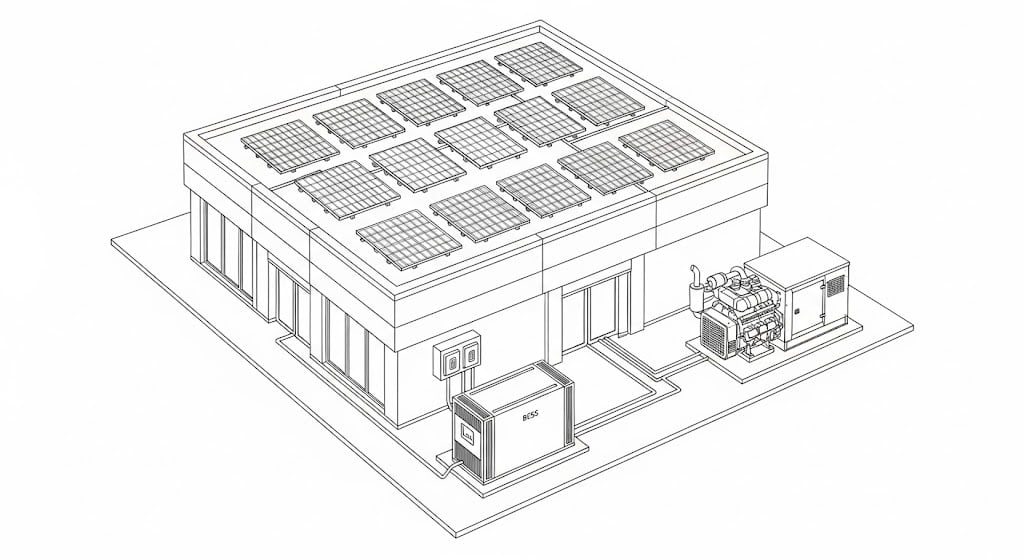
For decades, the generator was the only player in the backup power game. Now, it has a new, highly advanced partner: the Battery Energy Storage System, or BESS. A hybrid system combining a generator and a BESS offers capabilities that neither can achieve alone.
And, beyond just backup, a BESS can serve multiple roles:
Peak Shaving: Reduce electricity bills by discharging the battery to lower the building's energy consumption from the grid during the most expensive times of the day.
Power Quality: Act as a buffer to clean up "dirty" power from the utility, protecting sensitive equipment.
Grid Services: the battery controller (or EMS) can respond to a signal from the utility when there is a need for load-flexibility -- either reducing or shifting load. Utilities must procure this flexibility somewhere, and with modern EMS software, you can get paid for providing this service to the grid.
A commercial generator is a complex and expensive piece of machinery. To protect this investment, its controller is equipped with a network of sensors that act as a 24/7 nervous system, constantly monitoring the generator's health. Here are the key parameters the controller is always watching:
Engine Vitals:
Low Oil Pressure: This is the most critical safety feature. If oil pressure drops, it means the engine's moving parts aren't being lubricated. The controller will shut the engine down instantly to prevent it from seizing up and destroying itself.
High Coolant Temperature: If the engine starts to overheat, the controller will shut it down to prevent major damage like warped cylinder heads.
Engine Speed (RPM): The speed of the engine must be precise (e.g., exactly 1800 Revolutions Per Minute) to produce the correct electrical frequency (60 Hz). If it runs too fast (overspeed) or too slow (underspeed), the controller will shut it down to protect both the engine and any connected electronics.
Electrical Vitals:
Voltage: The controller makes sure the output voltage is within a safe range. It will shut down for overvoltage or undervoltage conditions to protect the building's equipment.
Frequency: As mentioned, this is tied to engine speed. Incorrect frequency can damage motors and sensitive electronics, so it's closely monitored.
When the controller detects a problem, it will issue either an alarm or a shutdown.
Alarm (Warning): This is for a less severe issue, like "Low Fuel" or "Battery Voltage Low." An amber light might illuminate, but the generator will continue to run. It's a signal that requires attention soon.
Shutdown (Fault): This is for a critical, equipment-threatening issue. A red light will illuminate, and the controller will immediately stop the generator. Examples include "Low Oil Pressure Shutdown" or "High Coolant Temperature Shutdown." This is a protective action to prevent catastrophic failure.
A backup power system that doesn't work when you need it is useless. The key to reliability isn't just buying good equipment; it's ensuring it's always ready to perform. The controller plays the lead role in automating this process through scheduled testing.
Generator Exerciser: Nearly every commercial controller has a built-in scheduler. A facility manager can program it to run a test on a recurring schedule (e.g., every Wednesday at 10:00 AM for 30 minutes). There are two main types of tests:
No-Load Test: The generator starts and runs for the programmed time without the ATS transferring the load. This is good for checking the engine, but it's like an athlete just stretching.
Loaded Test: The generator starts, and the controller also commands the ATS to transfer the building's load onto the generator for the duration of the test. This is a full-speed practice scrimmage. It makes the generator do real work, which is critical for verifying the entire system and for the health of diesel engines.
Battery System Testing: A BESS also needs its own health checks. The BESS controller will automatically and periodically perform self-tests. This can include a shallow discharge and recharge cycle to verify the performance and health of the individual battery cells and power electronics. This all happens seamlessly in the background.
Why Testing is Crucial:
Reliability: This is the #1 reason. It identifies potential problems (like a weak starting battery or a clogged fuel filter) during a planned test rather than during a real emergency.
Engine Health: For generators, the exercise cycle circulates lubricating oil, prevents seals from drying out, and burns off condensation. For diesel engines, a loaded test is vital to prevent wet stacking—a buildup of unburnt fuel and soot in the exhaust that occurs from running too long with no load.
Compliance: Many industries, especially healthcare and data centers, are legally required by standards like NFPA 110 to perform and log regular loaded tests to ensure the system is ready for life-safety functions. The controller's event log provides the proof of this testing.
When you add solar panels to a building that already has a generator and a battery, the controller's job evolves from a simple backup manager to a sophisticated energy asset dispatcher. Its primary goal is to use the cheapest, cleanest power first, while always being ready for an outage.
Think of the controller as the building's "Chief Financial Officer of Energy." It constantly asks and answers three questions:
What is the cheapest energy I can use right now? (Almost always solar)
What is the best way to prepare for a power outage? (Keep the battery charged and the generator ready)
How can I avoid high electricity costs from the grid? (Use the battery during peak price hours)
Let's look at how the controller manages the system in two primary modes:
During a normal day when the grid is stable, the controller's logic is all about saving money. It follows a clear priority list:
Priority #1: Use Solar Power. As soon as the sun comes up, the controller directs all available solar power to the building's loads. This is the cheapest and cleanest energy available.
Priority #2: Charge the Battery with Excess Solar. If the solar panels are generating more power than the building needs (e.g., on a sunny weekend), the controller uses that free excess energy to charge the battery.
Priority #3: Use the Battery to Avoid Peak Demand Charges. Many utilities charge extra for electricity during "peak hours" (e.g., 4 PM to 9 PM). The controller knows these times and will discharge the battery to power the building, avoiding the use of expensive grid power.
Last Resort: Use the Grid. The controller only draws power from the utility grid when solar isn't available and the battery is either depleted or being saved for peak hours.
In this mode, the generator does nothing. It remains in standby, ready for an emergency.
The moment the controller detects a grid outage, its priority shifts instantly from economics to reliability.
Battery-led system: The battery's inverter becomes grid-forming, creating a stable, independent microgrid for the building. The solar panels, seeing this stable microgrid, continue to operate and power the building.
Controller Monitors Battery State of Charge (SoC). The controller now watches the battery's charge level like a hawk. As long as the sun is shining, the solar panels will power the building and help keep the battery topped off.
Generator Starts on a "Low Fuel" Signal. The controller will only start the generator when the battery's State of Charge drops to a predetermined level (e.g., 30%). This is the "low fuel" signal for the building's microgrid.
Generator Supports the Load & Recharges the Battery. Once running, the generator's primary job is to power the building's loads. Any excess capacity it has is then used to recharge the battery, getting it ready for the next phase.
Generator Shuts Down to Maximize Renewables. Once the battery is sufficiently recharged (e.g., to 80% SoC), the controller will shut the generator off, allowing the building to run silently on the stored battery and solar power again. This cycle repeats as needed, ensuring the generator only runs when absolutely necessary, saving fuel and reducing noise.
This intelligent cycling ensures maximum use of renewable energy while guaranteeing the generator is available as the ultimate failsafe for a prolonged, multi-day outage.
Prime Mover: The engine that provides the mechanical power (e.g., a diesel engine).
Alternator: The component that converts the engine's mechanical rotation into electrical energy.
Fuel System: The tanks, pumps, and lines that deliver fuel to the engine.
Automatic Transfer Switch (ATS): A device that automatically switches the electrical load between the utility and the generator.
Open-Transition: A type of transfer that briefly disconnects from one source before connecting to another, causing a momentary power outage.
Uninterruptible Power Supply (UPS): A battery-based system that provides instantaneous, seamless power during an outage.
Controller/Microprocessor: The "brain" of the generator that automates its functions.
HMI (Human-Machine Interface): The screen and buttons that allow an operator to interact with the controller.
Annunciator: A panel of lights or a screen that displays the status and any alarms or faults.
BESS (Battery Energy Storage System): A complete system including batteries, inverters, and control software.
Inverter: A device that converts DC power from batteries to AC power for the building.
Grid-Forming: The ability of an inverter to create its own stable AC power grid (voltage and frequency) independent of the utility.
Grid-Following: The standard mode where an inverter syncs to and pushes power into an existing, stable grid.
Sensors: Devices that measure physical parameters and send data to the controller.
Common Monitored Parameters: Low Oil Pressure, High Coolant Temperature, Over-speed (engine running too fast), Over-crank (engine fails to start), and Under-voltage/frequency.
Safety Shutdown: An automatic procedure where the controller stops the generator to prevent damage.
Exercise Cycle: A scheduled, automatic test run of the generator under no load or a light load.
Load Bank Testing: A more intensive form of testing where an artificial electrical load is applied to the generator to test its performance under full capacity.
Energy Asset Dispatch: The process of a controller actively choosing which power source (solar, battery, grid, generator) to use at any given moment based on a set of priorities like cost or resilience.
Economic Mode: A control strategy focused on minimizing energy costs by prioritizing self-consumption of solar and using stored battery energy to avoid peak utility rates.
Resilience Mode: A control strategy that activates during a grid outage, focused on maintaining power to critical loads for the longest possible duration by intelligently cycling between solar, battery, and generator power.
State of Charge (SoC): The current charge level of a battery, expressed as a percentage of its total capacity (e.g., 100% is full, 0% is empty). This is the key metric the controller uses to make decisions in Resilience Mode.
